三维测量技术开始于20世纪60年代初,主要以非接触测量方式为主,随着世界上第一台红宝石激光器的创造,激光技术才逐渐应用于测量领域。测量技术后来被应用在汽车、航空等制造业还是得益于激光技术和电子技术的发展,同时测量的目标也由静态测量不断发展到动态跟踪测量以及三维立体测量。
由于科学技术的发展,三维激光测量仪已经在很大程度上提高了测量精度和效率,因此这一技术也逐渐成为了一项热门的研究,也成为了人们获取三维信息的主要技术手段。许多国内外的企业和研究机构都在这一领域进行着深入的探索,不断开发新的产品,应用在医疗,航天航空等的很多领域内。
在很多发达国家,研究人员不断深入对三维激光扫描技术的研究,并相继上市相应的扫描产品,形成了工业化的基本格局,同时,这些三维扫描产品的应用范围近年来,国内外学者在三维激光扫描技术领域进行了非常多的研究工作。从1994年开始,M.Levoy便带领他的团队使用高分辨率的彩色图像采集技术以及基于三角法原理的激光扫描仪,对米开朗基罗的主要雕塑作品进行了重建,并在此基础上研究了许多相关技术 [1] 。
1997年,在进行曲面三维扫描的过程中,Chia-Chun Huang在进行曲面三维点云的提取时,应用小波变换和快速傅立叶变换,从而提高了数据采集的工作效率 [2] 。另外,Wallace等人提出了三角法测量的修正公式,并通过实验验证了扫描对象的移动会给图像测量带来一些系统性误差 [3] 。接着,F.Xi等人推导出了一种关于线扫描误差特点的经验公式,并采用此公式补偿了三维点云的相关数据,获得了较满意的结果 [4] 。
1997年,加拿大国家研究委员会的El-Hakim等人将激光扫描仪和CCD相机固定在一个小车上,建立了所需要的硬件平台,获得了一个数据采集与配准系统,并于1998年在原有系统的基础之上,实现了可以对室内场景进行三维建模的系统 [5] 。
1999年,Zhao等人把两台互相垂直的三维激光扫描仪和CCD相机一起固定在一辆车上,实现了一个可以对数据进行动态获取的系统 [6] 。该系统的具体工作为:让汽车沿道路前行,被固定在车上的扫描仪用来拍摄道路两旁的建筑物,记录其表面的三维信息,照相机用于捕捉建筑物表面的颜色信息,再结合现实色彩的颜色信息将具有真实感的三维街区还原出来。这个系统可用于扫描如地面、建筑等大型场景。
2002年,I.Stamos和P.K.Alen实现了一个三维模型的完整系统,它通过获取大型建筑的彩色和深度图像,从而重建出具有照片真实性的室外建筑物模型。如今该系统常被用于历史古建筑的三维建模上 [7] 。
2006年,Simon Winkelbach和Sven Molkenstruck发明了一个被称为DAVID的桌面式三维激光扫描仪系统 [8] ,它的处理软件是这个系统的重要部分,像激光发射器、平面板、摄像头等硬件则需要自己购买,但由于这种扫描仪系统必须在黑暗的环境下进行工作,所以其适用范围大大减少。
发展到目前为止,美国和日本等发达国家已发展了数家高技术公司,并形成了一定规模的新兴产业,其产品精度高、速度快、易操作,并且已经运用于快速获取特定尺寸的三维立体模型中。
国内方面,华科大的图像识别与人工智能研究所和邦文文化发展公司经过两年的不断合作和努力,成功开发出了一个小型的三维激光扫描系统;首都师范的三维空间信息获取与应用实验室和中国测绘科学院合作研制出了一款车载激光三维扫描系统。当前,很多高校、科研院所正在使用激光扫描测量技术保护文物古建筑,雕塑,壁画等,这些实际应用表明,三维激光扫描技术在以后的国民经济发展中具有广泛的应用和发展前景。
在对国内外三维测量技术发展研究过后,本文决定针对假肢膝关节,探究一种便于三维测量的标定方法。因为膝关节是我们人体最复杂、最大的关节,它和相关的肌肉、肌腱彼此配合,可以实现人类优美且连贯的行走姿态。要想设计并加工出一个可以完全代替人体膝关节的假肢还是一个非常困难的任务。如果我们使用一些相对简单的机构装置替代假肢缺陷者的下肢,步态一定会不同于正常步态。为了使其更接近正常步态,实现优美连贯的步行,则需要针对设计加工出的膝关节面进行精确测量,并根据测量结果进一步优化结构设计以及加工工艺。
在针对假肢膝关节面的特殊形状进行探究后,决定利用激光三角法测量原理,搭建假肢膝关节面测量实验平台开展实验研究,采用一种基于激光三角测量法的简易相机系统标定方法,获得假肢膝关节面的点云数据,从而实现对被测假肢膝关节面的三维重建。
1. 测量系统原理
根据系统拟实现的功能,设计了测量系统的流程图,如图1所示。测量系统主要由线激光、精密转台、图像采集与处理系统组成,系统装置图如图2所示。系统主要工作流程包括:打开激光器,使线激光停在初始位置,将一个理想的激光线投射在线激光被测假肢膝关节表面上。同时,摄像机将拍摄到的图像传入计算机,完成一次拍摄后,运动控制器控制精密转台带动被测假肢膝关节转过特定的角度,重复进行扫描并拍摄,直到完成对被测假肢膝关节一周的测量后,即可通过计算机的matlab软件对所采集的图片进行除噪、平滑、二值化、校正等处理,获得被测膝关节表面轮廓的数据点,接着通过Geomagic Studio软件获取被测膝关节的点云图和表面轮廓图。
相机系统标定是指确定测量系统的结构参数,它的目的是为了得到被测物体的图像坐标和世界坐标之间的非线性关系。若系统不考虑相机畸变,则根据摄像机针孔模型,物像之间一一对应的关系,提出了一种比较简单的摄像机标定方法。在测量系统中,相机系统标定是非常关键的一个环节,对于整个系统的精度以及性能起着非常重要的作用。
2. 常用标定方法
在图像测量和机器视觉应用中,我们可以通过建立摄像机成像的几何模型来确定物像关系,即物体表面某个点的位置和它在图像中所对应点之间的相互关系,建立的几何模型的参数就是摄像机参数。通常情况下需要通过实验以及计算才可以得到这些参数,而这个求解的过程就被称之为摄像机标定 [9] ,其标定结果的精度及算法的稳定性将直接决定摄像机产生结果的准确性。
摄像机标定总的来说分为两种:传统的摄像机标定法和摄像机自标定法。传统的摄像机标定是在一定的摄像机模型下,利用相关数学变换的方法,对形状、尺寸已知的标定物进行图像处理,从而求得摄像机模型的内、外参数。它包括了两步法,利用最优化算法的标定法,双平面标定法,张正友标定法等;摄像机自标定法不依赖于标定参考物,仅仅通过摄像机在运动过程中对所拍摄的多幅图像之间的对应关系进行标定。它包括了分层逐步标定法、基于主动视觉的摄像机自标定法、基于二次曲面的自标定法等。
传统的摄像机标定法标定精度较高,并能够适用于任意的摄像机模型,但标定的过程相对复杂,最好是高精度的且已知相关结构信息的物体 [10] ;自标定方法只需要建立图像之间的对应关系,灵活性非常强,且潜在应用范围较广,但它并不是特别成熟,由于未知的参数太多,很难得到较稳定的结果。
一般情况下,传统的标定方法主要适用于精度较高的场合,并且摄像机的参数比较稳定,不会经常发生变化,而摄像机自标定法主要适用于精度相对来说较低的例如通讯、虚拟现实等场合 [11] 。
针对假肢膝关节的特殊结构以及实际情况,以及在对传统的标定方法进行了解和总结之后,本文采用了基于激光三角法的简易相机系统标定方案。
3. 基于激光三角测量法的简易相机系统标定方法
理想的摄像机成像模型是线性模型,或者称针孔模型 [12] ,我们都知道物体表面每个点的位置和它在图像中所对应点的位置一一相关,这是由光学成像的几何关系所决定的,它可用摄像机模型表示。摄像机在针孔模型下的成像几何关系如图3所示。
本系统在基于激光三角测量法原理下,仅使用一块垂直标定板便可以完成摄像机的参数标定,任取标定d板上的某点P,设其在世界坐标系中的坐标为(x,y),在图像坐标系中坐标为(xw,yw),两者之间的关系记为B = RA + T,如式(3.1):
(3.1)
其中,R为2 × 2旋转矩阵,T为2 × 1平移矩阵,即为:
(3.2)
将上式进行转换,可得如下表达式,记为:b = Ma,如式(3.3):
(3.3)
4. 实验及数据处理
在实验平台上固定摄像机、线激光器和制作的垂直标定板,将标定板放置在被测假肢膝关节所在的大概位置,打开激光器,使激光线尽量与垂直标定板重合,用摄像机拍摄标定板,然后把拍摄的图像传到计算机,通过matlab对图像进行角点检测,再根据各角点像素坐标值与所对应世界坐标值的关系完成摄像机参数的标定。
如图4(a)为制作的30 × 30 mm大小的棋盘格标定板,图4(b)为用摄像机拍摄出来的标定板,使用matlab软件进行角点检测,读取角点的坐标(xw,yw),再根据其实际坐标(x,y),代入式(3.3),求解出参数M,即可得旋转矩阵R和平移矩阵T (表1)。
5. 测量结果认证
物体三维轮廓的重建过程,就是在计算机中输入假肢膝关节面通过激光器扫描后的图像,再经过图像处理,获得许多个数据点,把所有的数据点收集到一起,组成一个三维数据场,通过这个数据场就能够对假肢膝关节的三维表面进行三维图像的重建,恢复出假肢膝关节的三维轮廓。
前文的系统标定完成后,我们便开始进行对被测实物假肢膝关节进行测量实验,然后对实验所得数据进行处理分析,并且主要进行了以下工作:
1) 采用维纳滤波法进行图像滤波;
2) 图像二值化;
3) 几何中心法提取结构光光条中心线;
4) 通过求取转台旋转中心以及旋转角度进行倾斜校正,获得假肢膝关节面形貌的点云数据;
5) 利用Geomagic Studio软件重建假肢膝关节面的三维轮廓。
由于假肢膝关节是由钛合金加工成的,表面比较光滑,呈银白色,易反光,拍摄出来的图片效果不是很好,故在实验前向假肢膝关节面喷射白色的显像剂,这样拍摄出来的图片较清晰,对后面进行图像处理也有很大的帮助。
将假肢膝关节的所有三维数据点输入到Geomagic Studio软件中,便可以获得假肢膝关节的点云图,如图5所示。
将点云图进行封装,并进行平滑处理,便可得到最终的膝关节三维轮廓图,如图6所示。
 (a)
(a) 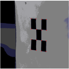 (b)
(b)
Figure 4. Calibration; (a) Checkerboard; (b) Collect calibration pattern
图4. 标定;(a) 棋盘板;(b) 采集标定图案
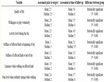
Table 1. Corner detection of coordinate values
表1. 角点检测坐标值
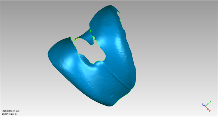
Figure 6. Three-dimensional contour of knee
图6. 膝关节的三维轮廓图
6. 总结
通过搭建假肢膝关节面测量实验平台开展实验研究,建立相机系统,并采用激光三角法测量原理和本文所提出的相机系统标定方案,测得一系列被测膝关节的图像坐标,在经过数据处理后得到被测假肢膝关节的旋转矩阵和平移矩阵,以便对下一步对该假肢膝关节的三维重建建立基础。
相机系统标定的方法众多,相机自标定以及新型的相机标定方法相对于传统方法有更好的灵活性和实用性,但其精度有待于进一步的提高。结合当前对于相机标定的研究和实际应用,可以采取一些措施,例如优化算法,提升摄像机硬件以及实验环境条件等方法提高相机标定的精度。